FIRE-FIGHTING HYDRAULIC PLATFORMS

MRP w.e.f. 01-07-2023
Validity till 31-12-2023
22-M Working Height
MODEL – FF220HD
(MRP – Rs. 3,95,00,000/-)
32-M Working Height
MODEL – FF320SHD
(MRP – Rs. 6,95,00,000/-)
42-M Working Height
MODEL – FF420SHD
(MRP – Rs. 7,95,00,000/-)
52-M Working Height
MODEL – FF520SHD
(MRP – Rs. 9,95,00,000/-)
56-M Working Height
MODEL – FF560SHD
(MRP – Rs. 11,45,00,000/-)
62-M Working Height
MODEL – FF620SHD
(MRP – Rs. 13,95,00,000/-)
70-M Working Height
MODEL – FF700SHD
(MRP – Rs. 17,95,00,000/-)
NOTE: All-inclusive prices
(with GST @ 18% on ALP,
Cab Chassis, Freight, TRC,
Training & Commissioning,
2 years Warranty).
EXTRA – All accessories like
Fire Pump, Escape Chute,
Radio Remote Water Monitor,
Thermal Imaging / IR Camera,
CCTV Camera, 4-WD Chassis,
AMC / CSMC contracts, etc.
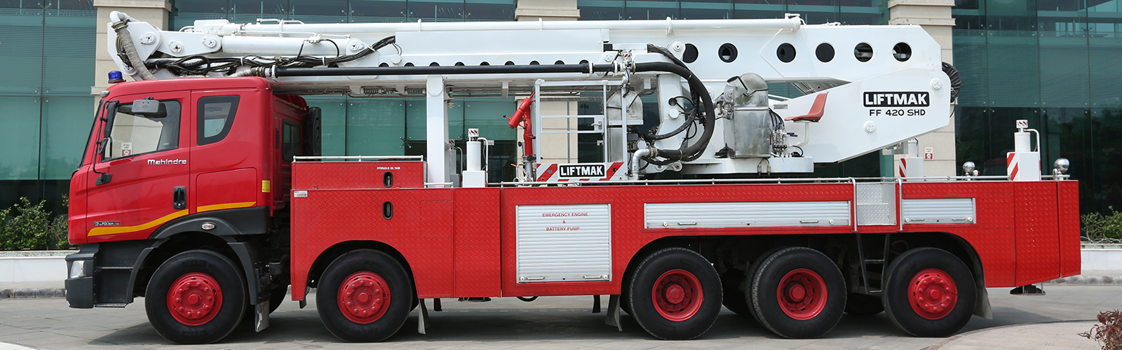
LIFTMAK Hydraulic Platforms are designed specifically for fire fighting and rescue. It comprises of one main boom with telescopic sections and an articulated boom* (*with or without telescopic extensions) with a Cage mounted at the end either directly or through a tip boom, to go up over and down the other side of obstruction.
The entire unit is mounted on a turntable fitted on a heavy-duty sub-frame on an ARAI certified BS-VI emission norms compliant chassis of minimum* 200 HP engine power (*150 HP in case of 22-m height). The total weight of the built up equipment is within the chassis GVW limit in line with prevailing CMVR guidelines.
Note: The chassis brand may be selected by the user in consultation with us – the chassis shall be equipped with company built driver’s cabin & an external PTO unit. We may need to modify chassis cabin and frame to facilitate the fitment of hydraulic platform on the chassis.
The Boom is box-type section and made of corrosion resistant high strength steel grade FE540 to IS 2062 Reaffirmed 2000/ ST55 (IS 961) or superior such as Weldox®/ Domex® or equivalent. The boom sections are internally and externally treated for corrosion resistance. The service points on chain-wheels (or on wire rope pulley system) and adjusting devices for the extending chain (or wire rope) are easily accessible for servicing.
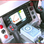
All the main systems in the Hydraulic Platform are controlled from signal inputs through redundant (dual information) sensors that automatically restrict the outreach and load to within safe limits. Outreach management as per design is controlled automatically by the Computer system/ CANBUS system. Electro-hydraulic proportional joysticks provide controlled and simultaneous movements of booms and slewing functions.
Graphic color monitors located at outrigger control station at vehicle rear, at turntable and at the cage dynamically display pertinent information about the hydraulic platform including height, reach, cage load, slewing, outrigger position, wind speed etc.
The cage has a rated load capacity of 500 Kg (with dry monitor) and is provided with ±45 degrees slewing. The hydraulic platform is tested for stability at 750 Kg cage load at maximum boom outreach and across 360 degree movement of the booms. Digital cage load display, with alarm and automatic cut-off, irrespective of reach, height or position of the hydraulic platform (with allowance for up to 20% overload) is provided.
In operating position, the equipment is stabilized on 4 nos. H-type (hydraulic in-out & up-down type) outriggers having sufficient power and stroke to lift all wheels of the vehicle off firm level ground and independent controls to level the vehicle on uneven (7 degree slope, fore and aft) terrain. An electronic vehicle auto-leveling system is provided to level the vehicle automatically to an accuracy of ±0.5 degree or better.
A slew restriction system is provided that automatically prohibits the slew movement on the side where the outriggers have not been fully extended. Electronic cage collision sensors are provided around the cage that cuts off the operation within approximately 1.0 meter of any obstacle; the cut-off can be over-ridden to continue the operation with caution.
A telescopic water pipe is provided made of stainless steel/ aluminium having nominal diameter of 75-mm. Moving sections of this pipe are thoroughly ground and chromium plated/ anodized to provide reliable function and long life. A water monitor is placed suitably at the cage having discharge capacity of 3800 LPM. The monitor is manually operated with facility of jet/fog nozzle (Optional – Electric operated Radio remote controlled Water Monitor).
A telescopic ladder* is attached on to main boom structure at several points throughout its length and front end in the telescopic sections, resulting in extreme stability even when operated in windy conditions. Each rung of the ladder is designed to support a load of 300 Kg without permanent distortion.
An inter-communication system is fitted between the turntable and the cage. Also, compressed breathing air supply from turntable to the cage is provided through a four way manifold at the cage with 4 nos. breathing air masks at cage and 4 nos. 6 litres @ 300 bar air cylinders positioned at the turntable. Please refer to our detailed technical catalogue for lost of other fitments & standard accessories provided with the equipment.
COMPUTER OVERRIDE SYSTEM: In case of failure or malfunction of the on board computer which controls all functions as well as takes care of the safety of the fire platform, the booms in normal course retract and return to transport position. Operation with computer override feature however makes it possible to over-ride the electronic computerized controlled system and operate the fire platform with modified reach parameters, with alternative mechanical/ hydraulic/ electric safety at full load, while ensuring hydraulic/mechanical/electrical safety systems in place to ensure stability of the hydraulic platform, with a modified reach diagram (* optional in 22-m HP model).
EMERGENCY BACK UP: In the event of failure of truck engine or PTO, a separate stand-by engine is provided to operate the equipment with reduced speeds and to stow the equipment; additionally, a battery driven back-up system is also provided for stowing purpose only.
For boom geometry & layout drawings of LIFTMAK Hydraulic Platform models, indicating maximum height, reach and dimensions in transport position, please reach us at the contact details provided.
| Technical Parameters | FF220SHD | FF320SHD | FF420SHD | FF520SHD | FF620SHD |
| Maximum working height from ground level | 22.0m | 32.0m | 42.0m | 52.0m | 62.0m |
| Maximum cage floor height from ground level | 20.0m | 30.0m | 40.0m | 50.0m | 60.0m |
| Maximum safe working load (without water monitor in operation) | 500kg | 500kg | 500kg | 500kg | 500kg |
| Maximum safe working load (with water monitor in operation) | 300kg | 300kg | 300kg | 300kg | 300kg |
| Maximum working outreach | 14.0m | 21.0m | 21.0m | 21.0m | 21.0m |
| Cage dimensions (outer) in mm ± 5% LxWxH | 1045 x 2050 x 1150 mm | ||||
| Test load for stability at full reach | 750kg | 750kg | 750kg | 750kg | 750kg |
| Continuous unlimited rotation in both directions | 360 degree, endless, continuous slewing | ||||
| Transport height less than | 3.8m | 4.0m | 4.0m | 4.0m | 4.0m |
| Transport length (chassis dependent) within | 9.0m | 10.0m | 11.0m | 12.0m | 12.0m |
| Transport width | 2.5m | 2.5m | 2.5m | 2.5m | 2.5m |
| Maximum outrigger width with both jacks fully extended | 7.5m (centre to centre) / Optional 6.0m outrigger span | ||||
| Maximum penetration of outrigger base plate below firm horizontal ground suitable to level vehicle on incline of | 7 degree | 7 degree | 7 degree | 7 degree | 7 degree |
| Maximum wind velocity | 12.5 m/sec | ||||
| Cage rotation (left and right) | 45° | 45° | 45° | 45° | 45° |
| Chassis GVW required | > 16 Ton | > 30 Ton | > 35 Ton | > 38 Ton | > 40 Ton |


")

")


")
")
